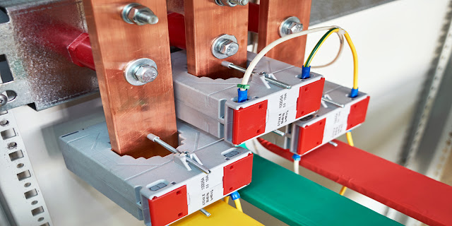
The effective connections in the conductors of
copper bars can be made very simply:
1.
Locking
2.
Tightening
3.
Riveting
4. Welding
5 methods of assembling copper bus bars (photo
credit: donalmccann.com)
Bolting and tightening are widely used on
site. Profile bars can be prefabricated using friction stir welding.
1. Bolted joints (most common)
Bolted joints are formed by
overlapping the bars and locking through
the overlap area. They are compact, reliable and versatile, but have the disadvantage
that the holes must be drilled or drilled in the conductors, which causes some
distortion of the current flow in the bar.
Bolted joints also tend to
have less
uniform contact pressure than those made by clamping, but
despite these problems, screw joints are very commonly used and have been shown
to be reliable.
They can be assembled on-site without difficulty.
2. Tight joints (most common)
Tight joints are formed by
overlapping the bars and applying an external
clamp around the overlap. Since there are no bolt
holes, the current flow is not disturbed, which decreases the strength of the
joint. The extra mass at the seal helps reduce temperature differences
under cyclic loads.
Well-designed clamps provide even contact
pressure and are easy to assemble, but take up more space
than a bolt-on, joint and are more expensive to manufacture.
3. Riveted joints (difficult, but…)
Riveted joints are similar to bolted
joints. They can be effective if done right. It is difficult to
control the contact pressure. They cannot be easily disassembled or
tightened in service and they are difficult to install.
4. Brazed or brazed joints (rare)
Welded or brazed joints are rarely used
for bars unless they are reinforced with bolts or clamps,
as heating under short circuit conditions can render them both mechanical and
electrical unresponsive.
5. Welded joints (not very sure…)
Welded joints are made by abutting
the ends of the bars and welding. They are compact
and have the advantage that the current-carrying capacity is intact since the
joint is effectively a continuous copper conductor. However, it may not be
safe or desirable to make welded joints in situ.
Welding copper is discussed in Copper
Development Association Publication 98, Profitable
Manufacturing: Joining Copper and Copper Alloys (download here).
Calculation of joint resistance
In principle, a tight or bolted connection is
achieved by joining two flat surfaces under controlled (and maintained)
pressure, as shown in Figure 6.
The resistance of a joint depends mainly on
two factors:
1.
The effect of rationalization
or resistance
to propagation, R s, due to the diversion
of current in the joint
2.
The contact resistance or interface
resistance of the joint, R i.
The total resistance of the joints, Rj, is given by: </ p>
Rj = R s + R i
This applies specifically to direct
current applications. When alternating currents are
flowing, one must also take into account changes in resistance due to skin and
proximity effects in the joint area.
Learn online courses and build creative, and
business skills to achieve your personal and professional goals. Join today to
get access to thousands of video courses on Lyskills. If you want to get
Physical training of all Electrical and Automations courses then visit BurraqEngineering Solutions.

